Link Basics
How a PCI Express Link Trains
Between power on and the first transaction, the two ends of a PCI Express link run a fixed sequence of states. Knowing that sequence is what turns a stuck link into a readable symptom.
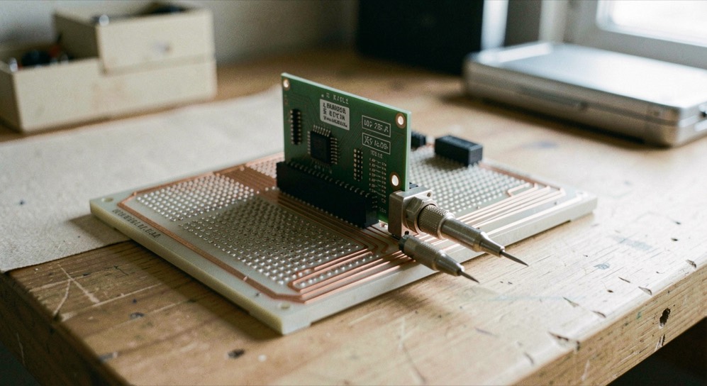
What comes up when a link comes up
A PCI Express link is not wide by default: during device initialization the two ends negotiate how many lanes will carry traffic, and either end can restrict the result. This page stays with what its source states exactly: the four traces in a lane, the negotiation of the width, the pins that hold the handshake, and what changes once the link is trained.
A link is a point-to-point channel between two PCI Express ports, carrying ordinary PCI requests, configuration, I/O or memory reads and writes, and interrupts, INTx, MSI or MSI-X, in both directions. Each device gets its own serial connection to the root complex, the host end of the tree, instead of sharing one set of address, data and control lines the way the older PCI bus did, arbitrated to one master at a time, in a single direction. A PCI Express link is full-duplex between its two endpoints, and concurrent traffic across multiple endpoints carries no inherent limitation.
The state machine that runs this sequence has a name in the specification of the interface beneath it: the PIPE specification, revision 7.1 of September 2025, Intel reference number 643108, calls it the Link Training and Status State Machine, or LTSSM, and its normative text names the states Detect.Quiet, Polling, Configuration, Recovery, L0, L0s, L1, L2, Loopback and Disabled. That document names them rather than defining them one by one, so what follows says what the states are called and what the specification shows them doing, and marks the rest as common industry usage. The desk now keeps a counted walk of the sequence for readers meeting the machine for the first time, and a page on the pause states that the same machine can hold.
Four traces, two pairs, no external clock
A lane is two differential signaling pairs, one to receive and one to transmit, four wires or signal traces in all, and it behaves as a full-duplex byte stream, moving data packets as eight-bit bytes in both directions at once. There is no external clock to distribute, because clocking information is embedded in the serial signal itself. That is the trade that buys the rates: a parallel interface races timing skew, signals arriving at different times on conductors of different lengths and velocities, and once the clock period drops below the widest arrival spread, the transmitted word cannot be recovered, which caps such a bus in the hundreds of megahertz against the multi-gigahertz range of serial signaling. In a multi-lane link, packet data is striped across the lanes, and peak throughput scales with the overall width. The PHY layer that implements the electrical side of this is described on the page on the PIPE interface.
Who decides how wide the link runs?
The lane count is negotiated automatically during device initialization, and either endpoint can restrict it. A single-lane card inserted into a multi-lane slot, x4, x8 and so on, comes out of initialization at the highest lane count both ends support. The standard defines widths of x1, x2, x4, x8 and x16, and up to and including PCIe 5.0 it also defined x12 and x32, which the Wikipedia article on PCI Express, read on September 6, 2026, calls virtually never used. When bad or unreliable lanes are present, the link can dynamically down-configure itself onto fewer of them, which reads as failure tolerance rather than as a fault. What each lane carries once the count is settled is treated on its own page.
The socket can misrepresent itself too. A x16 slot may wire only four lanes, accepting any card while providing four, and its line in a specification reads x16 (x4 mode), x16 (x4 signal), or the shorthand x16 @ x4. The table below collects the widths and where the page meets them. The naming habit behind that line, what a size word covers and what it leaves open, is read layer by layer in the page on form factor names.
| Width | Status in the standard | Where the page meets it |
|---|---|---|
| x1 | Defined width | Low-speed peripherals, an 802.11 Wi-Fi card for example |
| x2 | Defined width | No slot of its own; an x2 card uses the x4 mechanical size |
| x4 | Defined width | At PCIe 1.0, peaks near 1064 MB/s in one direction, level with PCI-X at 133 MHz and 64 bits |
| x8 | Defined width | One of the multi-lane slots an x1 card also fits |
| x16 | Defined width, largest in common use | Graphics adapters |
| x12 and x32 | Defined up to and including PCIe 5.0 | Called virtually never used |
The pins that hold the handshake
Training rests on services the edge connector provides. PERST# is the fundamental reset, listed in the pinout as link reactivation. REFCLK+ and REFCLK- form the reference clock differential pair, and CLKREQ# is the clock request signal. Presence has its own mechanism: the PRSNT1# and PRSNT2# pins are slightly shorter than the rest, so they only make contact when a hot-plugged card is fully inserted. WAKE# closes the set, pulled high from standby power to say the card is wake capable. The mechanical side, sizes, brackets, open-ended sockets that accept longer cards, sits on the page that walks through the card and the slot. The desk also keeps a page on who may order the link down, and one on the forces that seat the card the handshake depends on.
What changes once the link is trained?
Once traffic flows, communication is encapsulated in packets, and the transaction layer of each PCI Express port does the packetizing and de-packetizing of data and status-message traffic. The software view is quieter: PCI Express preserves backward compatibility with PCI, so legacy PCI system software can detect and configure newer PCI Express devices without explicit support for the standard, with the newer features left inaccessible. What a packet does once it leaves the link is traced hop by hop in the fabric crossing, and the older break this compatibility descends from is told in the PCI to Express transition.
The power budget moves as well. A x1 card is held to 0.5 A at +12 V, 6 W, and 10 W combined, while a full-sized x1 card, initialized and software-configured as a high-power device, may draw up to 25 W. A full-sized x16 graphics card may draw up to 5.5 A at +12 V, 66 W, and 75 W combined on the same conditions. Far above those numbers, the summary line of the source page gives a top speed of up to 242 GB/s, labeled dual simplex; what encoding leaves of that figure is a separate question, treated on the encoding and usable bandwidth page. Two newer pages extend the reckoning: what the usable rate is made of decomposes the headline figure, and what a revision keeps fixed sorts which parts of the link move between generations.
Reading a link that trained narrow
A narrow link, not a dead one, is what usually reaches the bench. The card sits in a x16 socket, the driver loads, and transfers never clear a x4 ceiling. Read the documentation before reaching for instruments: the slot line gives the electrical width away, and either endpoint may have restricted the count during initialization. Then work from the connector backward, reset and reference clock first. The connector end of that inspection has its own pages now: the care of the gold fingers, the drawing that specifies them, and, for the instrumented step that follows, what the bench controls first.
Checks that settle a narrow link
- Read the slot line in the board documentation: x16 (x4 mode), x16 (x4 signal) or x16 @ x4 means the socket wires fewer lanes than its length suggests.
- Question both ends before suspecting the card: the lane count can be restricted by either endpoint.
- Treat a link running on fewer lanes as lane information: down-configuration is what the link does when bad or unreliable lanes are present.
- On a hot-plugged card, confirm full seating first: the PRSNT1# and PRSNT2# pins are shorter than the rest, and presence only reads at full insertion.
- Re-read the power limits after boot: 25 W for a full-sized x1 card and 75 W combined for a full-sized x16 card apply only after initialization and software configuration.
Common mistakes
- Reading the socket as the link. A x16 slot can run at x4, and only the specification line or a measurement says so.
- Expecting a x16 card to fit a x8 slot. A card fits a slot of its physical size or larger, never a smaller one.
- Quoting 242 GB/s without its label. The source publishes the figure as dual simplex, up to, and how it divides is a separate question.
- Treating PCI and PCI Express slots as interchangeable. They are not, and the difference reaches motherboards and adapter boards.
On the next board that trains narrow, find the line that pairs the mechanical size with the electrical one, and ask which endpoint could have restricted the count. If the answer is neither, watch the link come up after a fundamental reset and see whether the width it settles on matches the width on paper. Where the two disagree, the connector is the first suspect, not the negotiation.
The bench side of the same question continues on three newer pages: what a bit error rate counts when a link is measured rather than read, what a second run adds to the first, and the sign-off list a delivered board owes its owner. The document side is covered by the archival read of a datasheet, the memory a change bar marks and the file a qualified part carries, and the arithmetic of overhead prices the column of small charges a delivered figure answers to.
The page behind these facts
Every figure here that carries a source comes from one document, the Wikipedia article on PCI Express, read on September 6, 2026. It is an encyclopedia entry rather than a specification: it summarizes the standard, names the body that develops and maintains it, and carries the tables quoted on this page, link widths, connector pinout, slot power. The state names come from a second document, the PIPE specification revision 7.1, read the same day. Neither document publishes a state by state walk, which is why this page does not print one.