Form Factors
Card, M.2 or cable: Choosing a link route
A PCI Express link can be built along three mechanical routes: a card in a slot, a module on an M.2 connector, or a cabled link between two connectors.
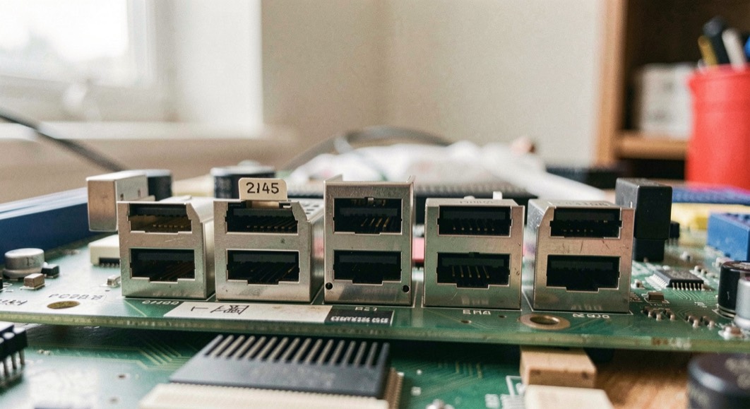
A PCI Express link can be built along three mechanical routes: a card in a slot, a module on an M.2 connector, or a cabled link between two connectors. Each route fixes a different set of mechanical facts, and each leaves a different set of problems to the designer. The choice is therefore not about which route is better, but about which set of constraints the enclosure, the service model and the budget can actually absorb.
The electrical layer does not change with the route. A x4 link trained at 8 GT/s behaves the same whether it crosses a slot, a module edge connector or a cable. What changes is who owns the mechanical risk: the slot specification, the module specification, or the designer's own cable and retention scheme. That distinction is the one worth carrying into a design review, and it is the same distinction that separates a tidy database client from a pile of ad hoc queries in older Mac software, a point the history pages at mac database software make in passing.
What does each form factor fix?
A card slot fixes insertion, retention, keying, power delivery and reference clock distribution. The card edge, the slot latch, the keying notch and the auxiliary power pins are all defined by the base specification and its CEM addenda. The designer inherits a known insertion force, a known card size envelope and a known thermal budget per slot. What the slot does not fix is the host side: lane count, bifurcation, slot power budget and airflow still depend on the platform.
An M.2 module fixes a much smaller envelope. The module specification defines the card dimensions, the keying, the mounting screw and the connector pinout for a family of modules. It does not define a retention latch, a hot plug story or a service procedure. The module is held by one screw and a connector, and the host must provide the standoff and the thermal path. In return, the module occupies a fraction of the volume of a slot and needs no card bracket.
A cabled link fixes almost nothing by itself. The cable assembly, the connector pair, the strain relief, the bend radius and the retention are chosen by the designer. The specification covers the signal integrity budget and the connector families, not the mechanical installation. That freedom is the point: a cabled link can cross a hinge, a bulkhead or a backplane where no slot or module can reach.
When is a cabled link the honest choice?
A cabled link is the honest choice when the two endpoints cannot share a board, a bracket or a chassis face. Three situations recur. First, when the device must be serviceable from outside the enclosure, so the connector becomes the service boundary. Second, when the two endpoints move relative to each other, as in a hinged lid or a sliding tray, and the cable must absorb the motion. Third, when the link must cross a midplane or a sealed wall where a slot would compromise the enclosure rating.
In each case the designer is buying reach at the cost of mechanical ownership. The cable must be specified for impedance, skew and bend radius, and the connector must be rated for the mating cycles the service model implies. If the service model is one insertion per year, a modest connector is adequate. If the service model is daily swapping, the connector becomes the dominant reliability item, and the honest choice may be to return to a slot or a module.
What does a module give up against a card?
A module gives up the bracket, the latch, the hot plug story and the generous thermal envelope. A card can be retained by a latch that survives vibration and can be removed without tools in some chassis. A module is retained by a screw, which is a tool, and by a connector whose mating cycles are finite. A card can be designed for a front panel with LEDs, connectors and a handle. A module has no front panel; its face is the board edge.
The thermal difference is the one that catches designers. A card slot usually has an airflow path defined by the chassis, and the card can carry a heatsink within the slot pitch. A module sits close to the host board, often under a shield or beside other modules, and its thermal path is whatever the host provides. A module that draws more than a few watts needs a deliberate thermal solution, and that solution is the designer's, not the specification's.
The three routes compared
| Route | What it fixes | What it leaves to the designer |
|---|---|---|
| Card in a slot | Insertion, retention, keying, power, reference clock, card envelope | Host lane count, bifurcation, slot power budget, airflow, bracket layout |
| M.2 module | Module dimensions, keying, mounting screw, connector pinout | Standoff, thermal path, retention beyond the screw, service procedure |
| Cabled link | Signal integrity budget, connector families | Cable assembly, strain relief, bend radius, retention, mating cycle budget |
The table is deliberately short. The useful question in a design review is not which column is longer, but which row matches the service model. A route that fixes retention but not service access is a poor fit for a field replaceable unit. A route that fixes reach but not retention is a poor fit for a vibrating enclosure.
A checklist before choosing
- Run the following before committing to a route.
- Count the lanes the endpoint needs, and confirm the host can supply them at the required rate without bifurcation surprises.
- Measure the available volume in three dimensions, including the space needed to insert and remove the device.
- State the service model: how often the device is inserted, by whom, and with what tools.
- State the thermal budget: watts at the device, ambient at the device, and the airflow the host can guarantee.
- List the mechanical loads: vibration, shock, cable pull, and the retention force the specification requires.
- Confirm the connector mating cycle rating against the service model.
- Confirm the reference clock and reset distribution reach the chosen route.
- Decide who owns the mechanical risk, and write that name into the interface document.
Common mistakes
- Treating the module as a small card. The module has no bracket, no latch and no chassis-defined airflow. A design that assumes card-like service access will fail at the first field replacement.
- Assuming a cabled link is plug and play. The cable is a designed assembly, not a commodity. Bend radius, strain relief and connector retention are all part of the link, and none of them are covered by the electrical specification alone.
- Choosing the route before the service model. The service model decides retention, mating cycles and access. Choosing the route first usually means reworking the enclosure later.
- Ignoring the reference clock. A route that carries data but not the reference clock forces the designer to add a clock source, which changes the bill of materials and the jitter budget.
- Forgetting the removal path. Insertion is usually easy to design; removal is where the fingers, the tool and the cable bend radius have to fit. A route that cannot be unplugged is a route that cannot be serviced.
- The three routes are not ranked. They are three answers to the same question, and the question is which mechanical facts the design can afford to own. The electrical link will train either way.
The page behind these facts
The figures on this page are read from the source the text names, pcisig.com, consulted on September 6, 2026. How this desk reads a document, and what it does with a figure it cannot source, is set out in sources and method.