Form Factors
Clearance and Keep-Out around an expansion card
A card needs clear space on both faces, along its edges, and beyond its far end.
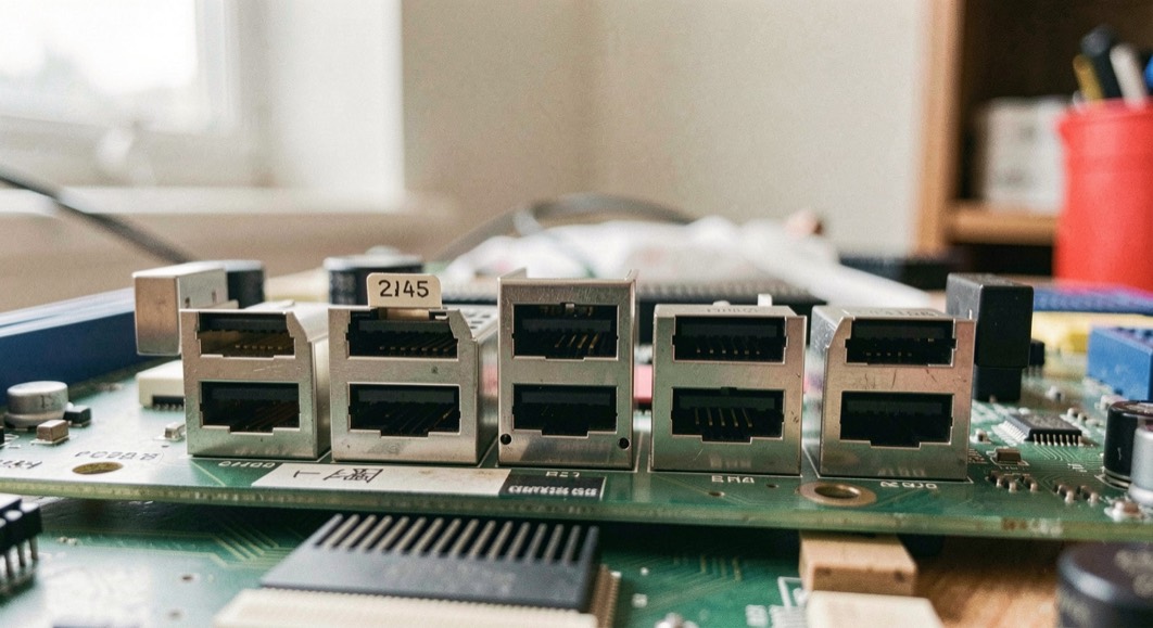
A card needs clear space on both faces, along its edges, and beyond its far end. The specification fixes the keep-out envelope around the connector and the card faces; the chassis fixes the rail span, the retention bracket, and the airflow path. Card length changes the answer because a longer card extends the keep-out zone further into the enclosure, where rails, cables, and drives may already sit.
What space must stay clear around a card?
The keep-out zone is the volume that must contain nothing but the card itself. It has four parts. The first is the component-side face, the side that carries the tall parts: heatsinks, inductors, and connectors. The second is the solder-side face, which is flatter but still needs room for the through-hole tails and any stiffener. The third is the card edge and the retention bracket, where the card meets the chassis. The fourth is the far end of the card, past the last component.
A practical way to think about it is that the card occupies a box, and the box has a margin. The margin is not decoration. It absorbs tolerance stack-up between the card, the connector, and the chassis, and it keeps the card from touching a neighbouring card or a cable. In a dense enclosure the margin is often the first thing to disappear, and the symptom is a card that seats but does not fit.
Anyone who has planned warehouse layouts knows the same idea in another form: the space a pallet needs is not the space the pallet measures. A guide such as industrial storage and handling practice treats clearance as a design input rather than an afterthought, and the same discipline applies inside a computer chassis.
Which clearances are set by the specification?
The PCI Express specification and its mechanical addenda set the connector dimensions, the card edge finger geometry, and the keep-out envelope around the add-in card. These are the numbers a card vendor must respect so that the card fits any compliant slot. They cover the card thickness, the height of components on each face, and the position of the notch and key. They also cover the bracket, which is a standard height and depth so that it lands in a standard chassis opening.
The specification does not set the distance from the card to the side wall of a particular enclosure, the length of the rails, or the position of the fan. Those are chassis decisions. This split matters when a card is described as "compliant": it means compliant with the card-side envelope, not guaranteed to fit every box.
| Clearance | Who sets it | What happens when it is missing |
|---|---|---|
| Component-side face height | Specification | Tall parts foul the adjacent card or the lid |
| Solder-side face height | Specification | Through-hole tails short against the chassis floor |
| Card thickness and key position | Specification | Card does not seat in the connector |
| Bracket height and depth | Specification | Card cannot be screwed down or exits the wrong opening |
| Rail span and card length support | Chassis | Long card has no support at its far end |
| Distance to side wall and drives | Chassis | Cable or drive presses on the card |
| Airflow path across the card | Chassis | Card runs hot despite a compliant envelope |
| Service space for removal | Chassis | Card cannot be extracted without dismantling |
How does card length change the answer?
Length is the variable that moves the keep-out zone the most. A half-length card ends well before the front of the chassis, so the far-end clearance is rarely a problem. A full-length card reaches into the region where drive cages, front fans, and cable bundles live. The card-side envelope stays the same in cross-section, but the volume it sweeps grows with every millimetre of length.
Three consequences follow. First, the far-end support: a long card needs a rail, a bracket, or a chassis feature that holds the end of the card so it does not sag or vibrate. Second, the cable route: a cable that crosses the card at mid-length may be fine on a short card and a foul on a long one. Third, the airflow: a longer card blocks more of the front-to-back path, so the chassis fan curve and the card's own cooling have to be considered together.
Length also interacts with the connector. A card that is mechanically long but electrically short, with the fingers only at the connector end, still occupies the full mechanical length. The keep-out zone follows the mechanical outline, not the electrical one.
Checklist for checking a card against an enclosure
- Work through these in order, with the card in hand and the enclosure open.
- Measure the card: length, height on both faces, and bracket depth.
- Read the chassis documentation for the maximum supported card length and the rail positions.
- Confirm the connector is the right key and generation for the card.
- Check the component-side face against the adjacent slot or the lid.
- Check the solder-side face against the chassis floor and any stiffener.
- Trace the cable route across the full length of the card, not just the connector end.
- Confirm the far end of the card is supported if the card is long.
- Verify the airflow path is not blocked by the card or its heatsink.
- Test extraction: can the card be removed without moving a drive or a fan?
- Re-check after the first power-on, since thermal expansion and cable settling can change contact.
Common mistakes
- Assuming a compliant card fits every chassis. Compliance covers the card envelope, not the enclosure.
- Measuring only the component side. The solder side has its own limit and its own failure mode.
- Ignoring the far end of a long card until the first vibration test.
- Routing a cable over the card because it fits at the connector end.
- Treating airflow as a separate problem from mechanical clearance. They share the same volume.
- Forgetting service access, so a card that installs cannot be removed in place.
Reading the numbers together
The specification and the chassis answer different questions. The specification says what a card may occupy. The chassis says what the surrounding volume may contain. A build works when both are satisfied at the same time, across the full length of the card, on both faces, and with the cables and airflow that the system actually needs. When a card does not fit, the useful move is to identify which of the two sets of numbers is being violated, because the fix is different in each case.
The page behind these facts
The figures on this page are read from the source the text names, pcisig.com, consulted on September 6, 2026. How this desk reads a document, and what it does with a figure it cannot source, is set out in sources and method.