Section 05
Topology
The tree a system walks at boot: root ports, switches, bridges and endpoints, and the addressing that lets software find each of them.
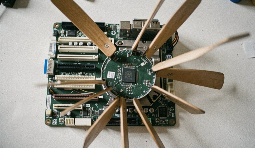
A tree, not a bus
The bus this interconnect replaced was shared: devices sat on the same wires and took turns. PCI Express is point to point. Every device has its own serial link back toward the host side component, and that component, the root complex, sits at the top of a tree. Nothing is shared except the path, and the path has a shape a reader can draw.
What a switch adds
A switch behaves like a network switch for this traffic. It has exactly one upstream port, pointing toward another switch or ultimately toward the root complex, and one or more downstream ports pointing toward further switches or toward devices. That is how a host with a limited number of native lanes ends up with far more slots than lanes. The distinction between a switch and a bridge, which product names use interchangeably and the specification does not, is worked through in bridges and switches.
How does software find any of this?
By walking the tree at startup and numbering it. Every device function carries its own configuration space, 256 bytes in the legacy model and extended to 4096 bytes here, and it is addressed by a bus number, a device number and a function number. Eight bits, five bits and three bits give up to 256 buses, 32 devices each and 8 functions each, a theoretical ceiling of 65,536 addressable functions in one system. Each non bridge device can implement up to six base address registers, each claiming a region between 16 bytes and 2 gigabytes, and firmware or the operating system programs them during that walk. The walk is described in enumeration and configuration space.
Adding and removing a device while it runs
Hot plugging is supported, and part of the mechanism is mechanical rather than logical: presence detect pins in the connector are made shorter than the pins around them, so a system can tell a card is fully seated before it brings the link up. That detail explains a class of intermittent faults that look electrical and are not.
What this section is careful about
Several words used constantly in this field, including endpoint as a formal device class, bridge as a device type and enumeration as a named process, could not be traced to a definition in a document the desk read. They are used here in their ordinary industry sense and the pages say so. The shape described above, root complex, switch, configuration space and addressing, rests on material the desk did read, and the words themselves are defined once in the glossary of the link.
The other doors of the publication: Link Basics, Generations, Form Factors, Compliance, Ecosystem and Bench Notes. Every one of them points back to the link speed table.
In this section
6 pages, newest first.
-
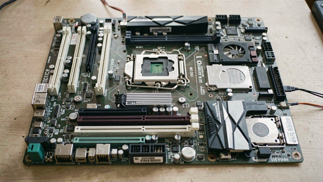
Root Ports, Switches and Endpoints
PCI Express is a tree, not a bus. Every device hangs from exactly one path back to the root complex, and most confusing symptoms come from misreading that path.
September 6, 2026
-
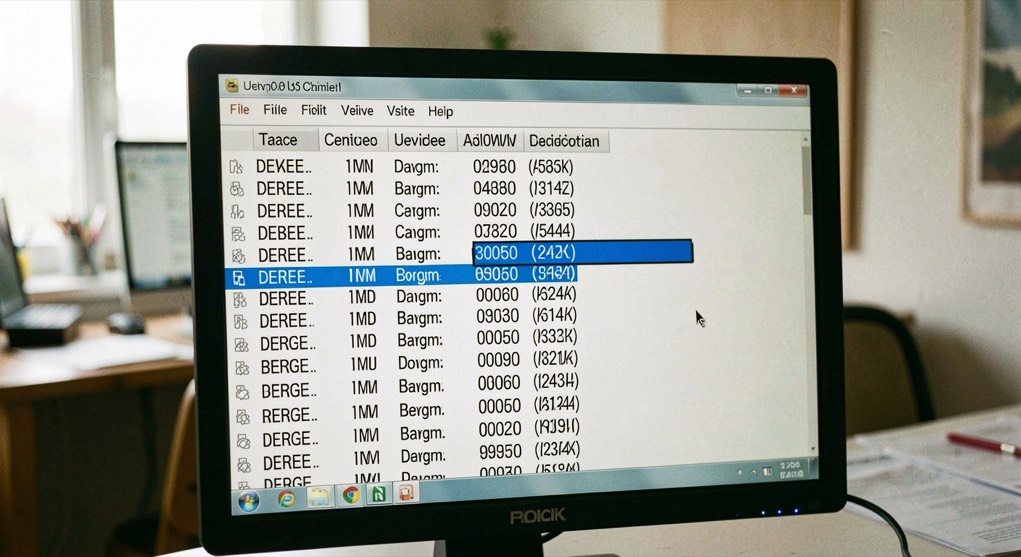
Enumeration and Configuration Space
Before a driver touches a device, something has to find it, number it and give it addresses. That walk is enumeration, and it explains most of what lspci prints.
September 6, 2026
-

How a packet crosses a switch fabric
The fabric is an itinerary, not a path: each link is its own channel, and the route behaves like the slowest leg it contains.
September 6, 2026
-

Reading a PCIe fabric as a graph
A PCI Express fabric is a graph: endpoints, switches, bridges, and a root complex are vertices, and links are edges.
September 6, 2026
-
-

Power and topology: One plan, not two
Power enters a fabric at defined entry points, usually a small number of connectors or busbars, and from there it is distributed along rails to every device in the tree.
September 6, 2026