Ecosystem
Bridges and Switches, and the Difference
Bridge and switch are used interchangeably in product names and never in the specification. The distinction is worth holding on to, because it decides what the software sees.
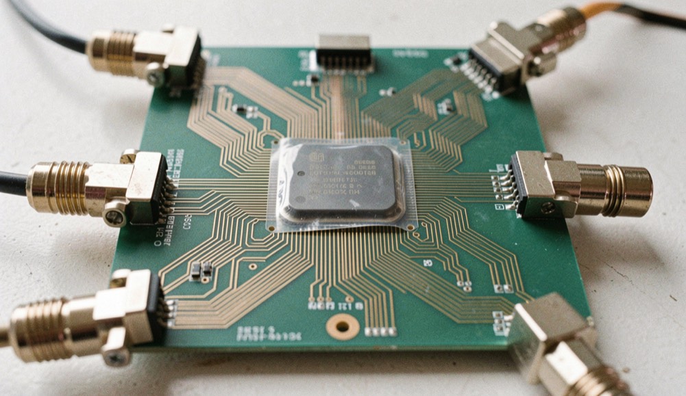
One catalog row, two different jobs
The archived index of this domain records a solutions catalog organized by product category, and one of the captured category paths is written "bridges/switches". The slash carries weight. The material read for this page on September 6, 2026, defines the pair in one line that splits in two: both are silicon that connects PCI Express segments together, but a bridge translates between PCI Express and another bus, while a switch fans a single upstream link out to multiple downstream ports. Treating the two words as synonyms hides which question to put to a datasheet.
One upstream port facing many downstream ports makes a switch. A second bus on the far side makes a bridge.
The distinction exists because of what a PCI Express fabric is. The standard replaced the shared parallel bus of conventional PCI with a point-to-point arrangement, in which every device connects to the root complex through its own dedicated serial link rather than sharing one bus with every other device. A link is a channel between exactly two ports, and it carries ordinary requests, configuration, I/O, memory read and write, along with interrupts in the legacy INTx form or the message-based MSI and MSI-X forms. Nothing in that description multiplies ports. These parts are what multiply them.
A bridge or a switch terminates a link and forwards traffic between two fabrics, so its behaviour is read from the same training, PIPE and enumeration rules that govern any other port. The board around it adds a second layer of questions: which reference clock is shared, how the reset tree is sequenced, and which lanes are re-driven before compliance is claimed. Those questions sit with the integrator rather than the protocol, and they are collected on the page covering what the integrator re-verifies, where the reference design is read against dated revision notes.
Where the category list comes from
The archived index of this domain shows the catalog organized by product category. Bridges/switches is the only captured path that names two devices in a single row, which is the reason this page exists.
What does a switch do with a packet?
The comparison the reference article linked above reaches for is a network switch, except that it works with PCI Express connections. Inside the tree topology, which the desk keeps on a page about root ports and switches, a switch has exactly one upstream port, connected toward a higher-level device, either another switch or the root complex, and one or more downstream ports, connected toward further switches or the devices at the ends of the tree. The working description fits in one clause: receive a packet from one port, forward it to an appropriate, different port. What that forwarding costs the packet, hop by hop, is walked in how a packet crosses a fabric.
That forwarding is what lets one upstream link be shared across several downstream ports, and the same page sets it against static lane bifurcation, a term the desk flags rather than asserts: common industry usage, not a word traced to a specification the desk read. Two consequences do rest on sourced ground. A switch is how one root complex port comes to feed more device slots than it has native lanes for, and the usual case stays asymmetric, one port up and many down, with the same page noting a multi-host topology that carries multiple upstream ports.
Why a board needs the fan-out at all
A root complex port is not short of bandwidth. It is short of places to plug things in. The point-to-point rule gives every device its own link, and a link is a two-party affair by construction, so the number of devices a port can serve equals the number of links it can terminate. A switch changes that arithmetic without breaking the rule: every link on its downstream side is still a point-to-point link between two ports, and each one negotiates its width during device initialization, where either side can restrict the count. Reaching the point where traffic flows is its own sequence, described on the page about how a link trains.
Where does the bridge actually sit?
The bridge gets one line in the same material, and the desk would rather report that thinness than pad it: silicon that translates between PCI Express and another bus. Translation is the job, so the test is directional. A part that ends one protocol and starts another is doing bridge work. A part that ends a link and starts several more of the same kind is doing switch work. A connector carrying two protocols side by side is doing neither: the ExpressCard slot described in the form factor material carried one PCI Express lane at 2.5 Gbit/s alongside USB 2.0 Hi-Speed at 480 Mbit/s, and sharing a connector is not translation.
The vocabulary itself needs a caveat. The desk searched the reference article it read for bridge, endpoint and enumeration, each used as a formal term, and did not find them there. All three run through block diagrams and firmware logs across this field. Until a document that defines them has been read, they stay marked as unverified on this page rather than dressed up as sourced.
The fixed arithmetic a switch fans out into
Splitting one upstream link into many downstream ports achieves little if the fabric cannot tell the resulting devices apart. Every device function carries its own configuration space, 256 bytes in the legacy PCI model and 4096 bytes from PCI-X 2.0 and PCI Express onward. Addressing follows a bus, device and function triple, and each non-bridge device, to use the material's own phrase, can implement up to six Base Address Registers, which system firmware or the operating system programs during enumeration, the step described under enumeration and configuration space. The widths, and the ceiling they produce, are in the table.
| Field | Value in the material |
|---|---|
| Bus number | 8 bits, up to 256 buses |
| Device number | 5 bits, up to 32 devices per bus |
| Function number | 3 bits, up to 8 functions per device |
| Configuration space per function | 256 bytes in the legacy PCI model, 4096 bytes from PCI-X 2.0 and PCI Express onward |
| Base Address Registers | Up to 6 per non-bridge device, each mapping a region of 16 bytes to 2 GB |
| Addressable device functions | A theoretical ceiling of 65,536 system-wide |
Two questions to put to a datasheet
Both come out of the definitions above, and a block diagram answers either one in a few seconds. Count the ports that face upward: one upstream port puts the part in the tree topology the material describes, more than one means the multi-host arrangement, a different design decision on both sides of the part. Then read the feature summary for the name of a second bus. A part that names one is doing bridge work. The material read here does not inventory which buses those are, so the part's own document has to say. Past the datasheet sits the file a part owes a design before the design trusts it: qualification is the name for that evidence.
A short harness for the part on the bench
- Count the upstream ports on the block diagram: one is the tree topology, more than one is the multi-host arrangement.
- Search the feature summary for the name of a second bus. That is where bridge work announces itself.
- Compare the lanes wired to a downstream port with the lanes the slot behind it supports, since the link settles on the highest count both sides support.
- Write down the revision and date of every document you quote, the way this page dates the material it read.
Common mistakes
- Reading "bridges/switches" as one device class. The slash separates a translator from a forwarder.
- Treating a connector that carries two protocols as a bridge. Coexistence on a connector is not translation.
- Quoting lane bifurcation as if a specification defined it. The desk could not trace the term to a document it read.
- Assuming a downstream port carries the full width of the upstream link. Width is negotiated per link, and either side can restrict it.