Topology
Root Ports, Switches and Endpoints
PCI Express is a tree, not a bus. Every device hangs from exactly one path back to the root complex, and most confusing symptoms come from misreading that path.
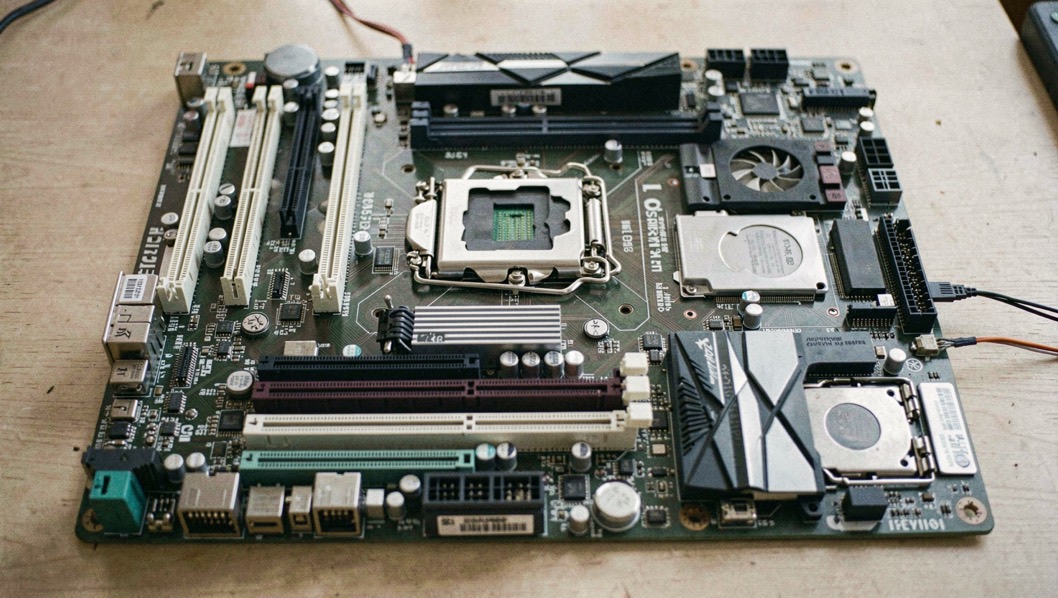
The trunk of the tree sits in the host
PCI Express did not only run faster than what came before. It changed shape: one host-side component at the trunk, a dedicated serial link for every branch, where the older PCI bus had one shared set of lines.
On the older bus, the host and every device shared the same address, data and control lines, and arbitration meant one master at a time, in a single direction. PCI Express replaced that shared topology with a point-to-point one: every device connects to the root complex through its own dedicated link. The root complex is the host-side component, typically integrated into the CPU or chipset; in the ecosystem material, chipset, or core logic, is the silicon that provides a system's root complex and its PCIe root ports. How much of the older bus survived that change of shape, and how much did not, is the subject of the PCI to Express break.
Over such a link, both sides send and receive ordinary PCI requests, configuration, I/O or memory read/write, and interrupts, legacy INTx or the message-based MSI and MSI-X. For the standard around all of this, the desk also keeps the general PCI Express article, read on September 6, 2026.
What a switch adds that a slot cannot
A connection carries one device at each end, so one port from the root reaches exactly one thing. A switch is what breaks that limit. It behaves like a network switch for PCIe traffic: in the tree-shaped topology it has one upstream port toward a higher-level device, another switch or ultimately the root complex, and one or more downstream ports toward further switches or devices. It receives a packet on one port and forwards it to a different port, so the upstream bandwidth is shared across the downstream ports by packet switching, and a single root complex port fans out to far more slots than it has native lanes for. What one of those packets actually does at each hop, credit by credit, is followed in how a packet crosses the fabric. A more advanced multi-host topology gives a switch several upstream ports. The silicon side of switching sits in the ecosystem section of this desk.
A root port, a switch and an endpoint each hold a position in the fabric, and the paths between them decide what a configuration request can reach. Enumeration walks those paths one device at a time, so a switch that forwards a request to the wrong port, or a loop that returns it to a device already visited, changes the tree the software believes it sees. Reading the fabric as a graph makes those cases visible: nodes for devices, edges for links, and a check of reachability and loops before any address is assigned.
Root ports, switches, and endpoints form the hierarchy that configuration space describes, and reading that hierarchy is a matter of walking the bus, device, and function numbers until no further device responds. The walk stops at the last valid function, which is why a missing endpoint and an empty slot can look alike from software. A newer page treats this as an inspection rather than a search, covering topology and enumeration with dated revision notes, and is worth reading alongside this one: stopping the walk.
Root ports, switches, and endpoints are usually read as a topology first: which port sits upstream, how many links fan out below it, and where enumeration stops. That view leaves the electrical side implicit, even though link width, lane count, and the power budget of each slot shape what the topology can actually support. A companion page treats those two threads together, following a fabric from the root complex down to the endpoint while tracking supply rails, slot power limits, and the constraints they place on configuration. Readers who want that combined reading can start where power enters.
One term the desk handles with care
Bifurcation, splitting the lanes of one x16 or x8 slot into several electrically independent links, set by firmware or by a switch downstream of the slot, is common industry usage rather than something the desk could trace to a document it read.
How many functions fit under one root?
Every function on the tree carries a three-number address: an 8-bit bus number, a 5-bit device number, a 3-bit function number. Each function owns a configuration space, 256 bytes in the legacy PCI model, extended up to 4096 bytes starting with PCI-X 2.0 and PCI Express. Each non-bridge device can implement up to six base address registers, each mapping between 16 bytes and 2 gigabytes into I/O port or memory space, and firmware or the operating system programs them, telling the device where its resources live. The walk around that space, enumeration and configuration space, has its own page.
| Quantity | Value |
|---|---|
| Bus number | 8 bits, up to 256 buses |
| Device number | 5 bits, up to 32 devices per bus |
| Function number | 3 bits, up to 8 functions per device |
| Functions, system-wide | 65,536, a theoretical ceiling |
| Configuration space | 256 bytes legacy, up to 4096 bytes |
| Base address registers | Up to 6 per non-bridge device |
When does a link settle its width?
A link is trained, not assumed. Lane count is negotiated automatically during device initialization, either side can restrict the width, and the link can down-configure to fewer lanes when bad or unreliable lanes are present, which is a form of failure tolerance. The standard defines widths of x1, x2, x4, x8 and x16, and up to and including PCIe 5.0 it also defined x12 and x32, which were virtually never used. The PHY Interface for the PCI Express, SATA, USB 3.2, DisplayPort and USB4 Architectures Specification, revision 7.1, September 2025, Intel reference 643108, read on September 6, 2026, names the machine that walks a link up, the Link Training and Status State Machine, and lists its states: Detect.Quiet, Polling, Configuration, Recovery, L0, L0s, L1, L2, Loopback and Disabled. The names are on the page. What each state does in detail is not, and the desk will not narrate it as if it were. How a link trains has its own page.
What a failing branch takes with it
An error casts a shadow shaped like everything below it. Downstream Port Containment is defined in section 6.2.11 of the PCI Express base specification, revision 7.0. When it is supported, a detected error disables the link to the entire sub-hierarchy below the faulting device, and every device in that sub-hierarchy stays inaccessible until the link is reset and a subsequent slot-reset step completes. Advanced Error Reporting, section 6.2 of the same revision, is the reporting side: on platforms that support it, a faulting device may already be accessible at the very first step of a Linux kernel error-recovery sequence, the one called Notification. Hot-plug rests on a small physical detail: the PRSNT1# and PRSNT2# presence pins are slightly shorter than the pins around them, so the system can confirm a hot-plugged card is fully seated before the rest of the link is brought up.
Three words the desk leaves unpinned
"Endpoint" as a device class, "bridge" as a device type, "enumeration" as a named process: all three run through PCIe writing, including the paragraphs above, and none was found defined in the material read for this page. They are common industry usage rather than something the desk could trace to a document it read, and they stay that way until the base specification itself is opened. The tree, the switch, the addressing and the containment behavior can all be read without those words being formal.
What to check on your own machine
- Count the lanes your platform wires to each long slot, and note any slot that is x16 in size but fewer in lanes.
- Pick one device and find its bus, device and function numbers in your system's listing.
- Open a device's configuration space and see how much of the 4096 bytes it fills.
- Check whether your platform reports Downstream Port Containment, and which sub-hierarchy a failed link would take offline.
- Name the ten LTSSM states listed in the PIPE document before reading any longer description of them.
Common mistakes
- Quoting "endpoint", "bridge" or "enumeration" as if a document read here defined them.
- Reading the LTSSM state names as a description of what the states do.
- Counting slots instead of links: one link ends at one device, and fan-out needs a switch.
- Confusing the 256-byte legacy configuration space with the 4096-byte extended one.
When a board misbehaves, establish three things first: the failing function's three numbers, the switch port it sits behind, and whether the sub-hierarchy below that port is what went quiet. The topology already gave you the address of the branch. The rest is reading.