Section 03
Form Factors
The card electromechanical slot, the M.2 keys, the storage connectors and the cabled variants that carry the same electrical link in a different shape.
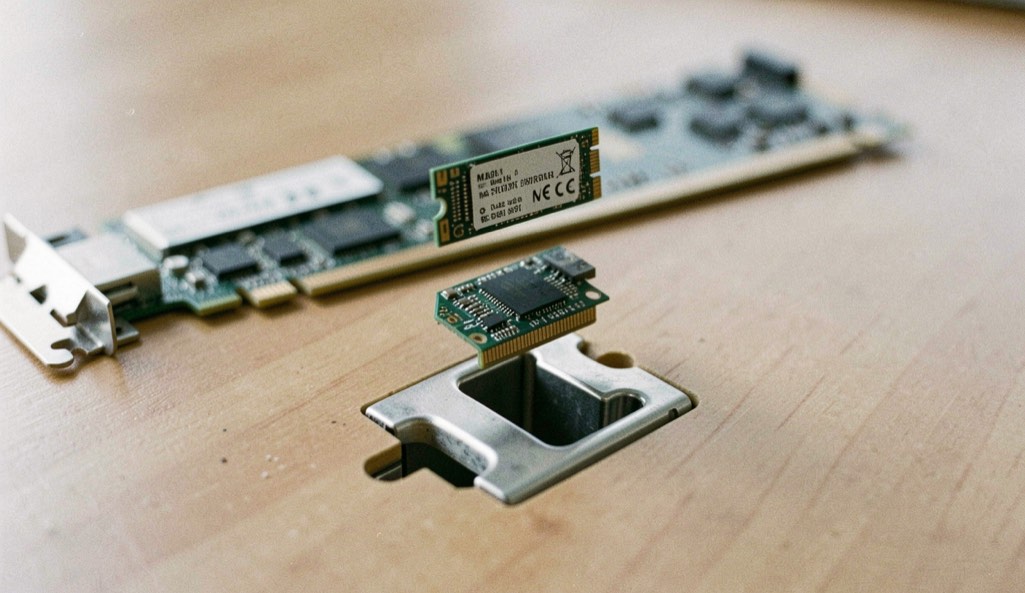
The same link in different bodies
PCI Express is an electrical and logical link, not a shape. The same lanes appear in a card edge connector, in a small module screwed flat to a board, in a storage drive bay and in a cable, and the differences between those shapes are mechanical, thermal and commercial rather than protocol level. Reading a form factor is therefore mostly reading what it is allowed to carry and how much power it can deliver.
The card edge connector
A full size add in card meets its slot through an edge connector with a keying notch between pins 11 and 12, which separates the data pins from the power pins and is what makes a short connector mechanically compatible with a longer card. Standard card heights are 111.15 mm and 68.90 mm, and standard lengths are 312.00 mm, 254.00 mm and 167.65 mm. Slot power scales with the connector: a x1 slot delivers up to 0.5 A at 12 V, wider slots up to 2.1 A, and a full size x16 graphics slot up to 5.5 A after initialization. Auxiliary connectors add 75 W or 150 W each, and the 12VHPWR connector adopted as part of the fifth generation card electromechanical specification can deliver up to 600 W to one card. The detail is in the card slot explained.
What does the letter on an M.2 socket actually restrict?
It restricts which signal sets the socket may carry, and nothing else. The A and E keys expose two PCI Express lanes plus USB 2.0 and a set of low speed buses, and are used for wireless modules. The B key exposes SATA, two PCI Express lanes and USB. The M key exposes SATA and four PCI Express lanes, which is the arrangement behind most high performance storage. Module sizes follow a width and length code: 22 mm wide, and 42, 60, 80 or 110 mm long. A module that fits mechanically can still be refused electrically, and the reason is usually the key. That is covered in M.2 keys and module sizes.
Drives and cables
U.2, formerly SFF-8639, was released in December 2011 and renamed in June 2015. It carries up to four PCI Express lanes and two SATA lanes through one mechanical connector, which is how a single bay accepts drives speaking three different protocols. OCuLink, released in October 2015, is the cabled version: version 1.0 carries up to four third generation lanes, and OCuLink-2 corresponds to fourth generation x4 or x8.
Two form factors worth knowing about
ExpressCard, created in 2003 to replace the PC Card standard on laptops, carried one lane plus USB in two widths, reached version 2.0 in March 2009 and never achieved wide adoption. Compute Express Link went the other way: rather than defining a new physical layer it reuses this one, moving from the fifth generation electrical interface in 2019 to the sixth in 2022 and doubling again in 2025.
The other doors of the publication: Link Basics, Generations, Compliance, Topology, Ecosystem and Bench Notes. Every one of them points back to the link speed table.
In this section
2 pages, newest first.
-
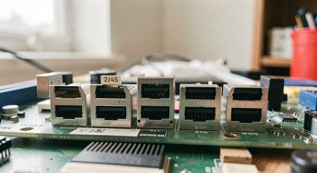
The Card Slot, Read End to End
The card electromechanical connector is the part of PCI Express most people can actually see. Almost everything about it is a clue to how the link will come up.
September 6, 2026
-
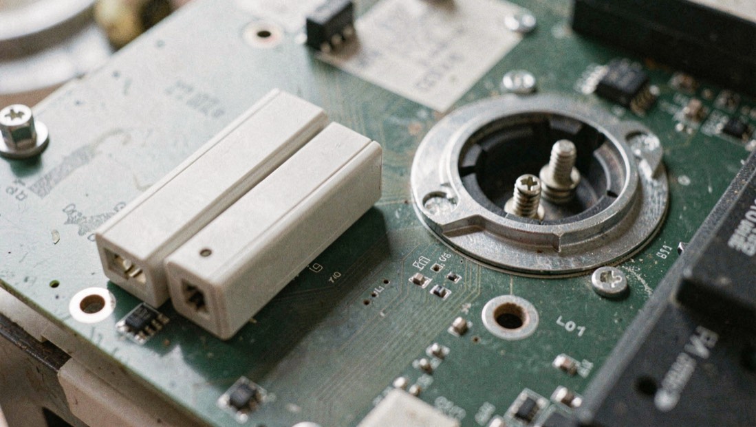
M.2 Keys, Module Sizes and What Fits
An M.2 socket is a mechanical filter on an electrical question. The key tells you which signal sets the socket may carry, and it is only half of the answer.
September 6, 2026