Form Factors
The Card Slot, Read End to End
The card electromechanical connector is the part of PCI Express most people can actually see. Almost everything about it is a clue to how the link will come up.
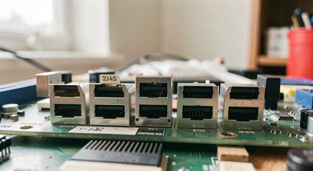
A slot makes two promises, and they are not the same promise
The PCI Express add-in card slot is an edge connector: the card is the plug, its copper fingers seated in the board. A key notch between pins 11 and 12 divides that edge, power and sideband on one side, the high-speed data pairs on the other. The same notch is why the shorter connectors work at all: a card keyed for x1, x4 or x8 enters a longer slot and stops where its edge stops, at pin 18 for x1, pin 32 for x4 and pin 49 for x8. Those end points are read from the material of September 6, 2026. The same edge, read as a plated surface that wears, is the subject of the care of a card edge, and the forces its springs and latch are specified for are walked in insertion force and retention.
Why does an x16 card not fit an x4 slot?
Because the fit runs one way. A card goes into a slot of its own physical size or larger, so an x4 card sits in an x16 connector while an x16 card has nowhere to land in an x4 socket. Some sockets are cut open at the end so a longer card can seat, but the default rule is the notch positions. Widths with no slot of their own take the next size up: an x2 card uses the x4 outline, an x12 card the x16 outline.
The outline has numbers of its own. Standard height is 111.15 mm, low profile height is 68.90 mm, and the standard lengths are 312.00 mm (full), 254.00 mm (three-quarter) and 167.65 mm (half). The length levels beside full are not a PCIe standard but a manufacturer agreement. What the standard does fix is the 57.15 mm (2.250 in) between the key notch and the end of the card, which keeps a seated card from protruding past the chassis wall.
What a slot label tells you, and what it does not
Mechanical size and electrical width are separate statements. A board can route fewer lanes to a slot than its outline suggests; the reference example is a x16 connector wired for four lanes. Board makers write that as "x16 (x4 mode)", and notation like "x16 @ x4" also circulates, though this is common industry usage rather than something the desk could trace to a document it read. The lane count is not fixed by the connector either: it is negotiated during device initialization, and either endpoint can restrict it. That negotiation is described on the page about how a link trains. What a name like "x16 (x4 mode)" does and does not promise is the subject of what a name covers. The full pin assignment is laid out in the reference article on PCI Express.
The slot on the board is only one of the mechanical routes a PCI Express link can take. The same electrical link also appears as a card edge in a connector, as a module seated in its own socket, and as a cable running between two enclosures, and each route carries its own pinout, retention and signal integrity constraints. Readers who need the full mechanical picture, rather than the slot alone, will find it in the newer page on card, module or cable, which treats the three routes side by side with dated revision notes.
Un emplacement de carte se lit d'abord par ses cotes : pas des broches, encoche de détrompage, hauteur de la carte, dégagement au-dessus du connecteur. Ces chiffres viennent des dessins de connecteur publiés dans les spécifications, et chaque cote porte une révision et une date. Une lecture attentive distingue ce qui est imposé de ce qui est seulement recommandé, et repère les tolérances qui décident de l'assemblage. Pour la méthode pas à pas, avec les renvois datés aux figures, voir the revision block.
Slot dimensions describe where a card seats and how its edge connector meets the receptacle, but they do not describe the volume the card and its components occupy once installed. Clearance is a separate question, governed by keep out zones around the connector, the bracket, and the adjacent slots, and it decides whether a card with a tall heatsink or a rear shroud fits at all. A newer page on the reading desk covers clearance around a card, including the keep out envelopes and the mechanical figures that apply per form factor.
One connector, several links
Carriers that hold several drives behind one connector split the lanes of a x16 or x8 slot into independent smaller links, x8+x8 or x4+x4+x4+x4, set by platform firmware or by a PCIe switch downstream of the slot. The practice is usually called bifurcation. The desk reads it as common industry usage rather than something it could trace to a document it read.
How much power does the slot owe the card?
Every card may draw up to 3 A at +3.3 V, which is 9.9 W. The +12 V budget scales with the connector; the figures below come from the card electromechanical material read for this page.
| Card class | +12 V limit | Combined from the slot |
|---|---|---|
| x1 card | 0.5 A at +12 V (6 W) | 10 W |
| x4 and wider | 2.1 A at +12 V (25 W) | 25 W |
| Full-size x16 graphics card, after initialization | 5.5 A at +12 V (66 W) | 75 W |
Beyond the slot, optional connectors add 75 W on six pins or 150 W on eight, for up to 300 W. Two 8-pin connectors, 375 W, were newly standardized in the PCI Express 4.0 CEM specification of 2018. The 12VHPWR connector, adopted as part of the PCI Express 5 CEM specification, raises the ceiling to 600 W, and the 12V-2x6 revision introduced in 2023 with PCIe CEM 5.1 changed the sockets so the sense pins only make contact once the power pins are seated. A 48 V connector carried into PCIe-CEM 5.1 of 2023 uses two current-carrying contacts rated 15 A continuous, and carries 720 W.
Those are sustained figures. Since an engineering change notice to PCIe-CEM 5.0, the added power connectors must tolerate a 100-microsecond draw at 3× the maximum sustained power, easing back to 1× at the one-second window, and slot power gained a similar 2.5× allowance in CEM 5.1. That limit is granted only after software configuration, once the Set_Slot_Power_Limit message has been sent; the notice belongs to ATX 3.0, CEM 5.1 to ATX 3.1.
What survives when the card leaves the motherboard?
The same interface has been re-hosted in connectors that look nothing like a slot. OCuLink, a cable version of PCI Express developed by PCI-SIG, reached version 1.0 in October 2015 with up to four PCIe 3.0 lanes, 3.9 GB/s over copper; OCuLink-2 carries 8 GB/s or 16 GB/s, the per-link figures behind PCIe 4.0 x4 and x8, set against the other widths in the link speed table. U.2, renamed from SFF-8639 in June 2015 after the specification's release on 20 December 2011, carries up to four PCIe lanes and two SATA lanes. M.2 puts up to four PCIe lanes and one SATA 3.0 port behind a single keyed edge connector, which is how one socket takes both a SATA module and an NVMe one; the keying is set out under M.2 keys and module sizes. The material ties hot plugging to ExpressCard, OCuLink, CFexpress and U.2, which is why a slot's presence pins are shorter than their neighbours: the system confirms a card is fully seated before the link comes up. The states that link can then be held in or ordered out of are separated on two newer pages: the pauses inside training and the deliberate stops.
Common mistakes
- Reading a slot's outline as a lane count. Notations like "x16 (x4 mode)" exist precisely because the two differ.
- Assuming a full-length card fits a short chassis. The length levels beside full are a manufacturer agreement, not part of the standard.
- Adding a 150 W rating to a budget without checking the sense pins: a 6-pin plug in an 8-pin receptacle reports itself through a missing Sense1, and the card stays within 75 W.
- Expecting a desktop slot to hot-plug. The material names ExpressCard, OCuLink, CFexpress and U.2.
Measure the connector before you order the board
None of this resists a tape measure and the board maker's documents. When the measurement moves off the connector and onto the link itself, the conditions have to be fixed first: what the bench controls before measuring is the page that names them.
Checks worth running
- Measure card height against 111.15 mm and 68.90 mm, and decide which one the chassis is built for.
- Measure 57.15 mm from the key notch to the end of the card, and hold it against the chassis rear wall.
- Count the fingers on a card's edge and match the count to pin 18, pin 32 or pin 49.
- Find the board maker's notation for each slot and separate what is mechanical from what is wired.
- Add the slot's power figure to the aux connectors, then check the total against the excursion limits in the material.