Reference · Ecosystem
The Solutions Catalog, Category by Category
This address used to hold a roster of catalog participants. The roster itself is gone and is not reconstructed here. Its structure survives in the archive, and the structure is the useful part.
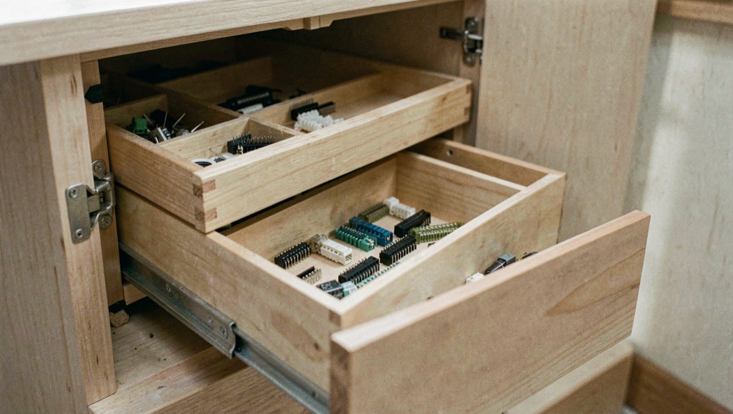
Nineteen shelves, and what each one held
A solutions catalog is a census of what the industry was shipping. Read shelf by shelf, it doubles as a map of the interconnect.
This domain once carried a solutions catalog for PCI Express architecture, an index organized by product category. This page reads its archived index. Nineteen category paths were captured from it, from asic to tools and test equipment, and that list is the whole recorded content of the roster: the page itself names no company at all. The order below is the desk's, grouped by the job each shelf does.
One caution first: nothing in the captured paths records a test result, so an entry says what a vendor shipped, never what a product passed. The evidence that turns a shipped part into a part a design may trust is the subject of what qualification owes a part.
Where does the silicon in a lane come from?
Start with the four shelves that describe a supply chain. An asic is a chip custom designed and fabricated for one function, a fixed PCIe switch or controller, rather than a general-purpose reprogrammable part. An fpga or pld is that reprogrammable counterpart: configurable logic, changed after manufacturing, used to implement or prototype endpoints, root ports and switches. An ip house licenses reusable, pre-verified logic, a PCIe controller or PHY design, to chip makers, selling building blocks instead of finished chips. A foundry is the fabrication plant where asics and PHYs are built once someone has designed them.
The fifth silicon shelf is not hardware. A bfm, a bus functional model, is a simulation-only model of a PCIe device or host used in pre-silicon verification, so that a controller's logic is exercised before any real silicon exists. The desk treats these definitions on its page for IP cores and verification models.
The parts that steer the packets
Two more shelves exist because a point-to-point link does not fan out on its own. Bridges and switches are silicon that connects PCIe segments: a bridge translates between PCIe and another bus, a switch fans one upstream link out to multiple downstream ports. The switch works like a network switch, receiving a packet on one port and forwarding it to another, so bandwidth is shared across the downstream ports, which static lane splitting cannot do. Chipset and core logic is the platform end of the same job: historically a northbridge and southbridge, on current platforms a platform controller hub, holding the system's root complex and its root ports alongside other I/O such as SATA and USB.
Read together, these shelves draw the tree the catalog hangs from: a root complex at the top, switches below it, one dedicated serial link to every device, in place of the older shared parallel bus. The desk keeps the port-by-port detail on its page for switches, root ports and endpoints.
What plugs in, and what it may draw
Connector and mechanical is the shelf you can hold: edge connectors, card guides, retention mechanisms, and cabling hardware such as the CEM connector, M.2, U.2 and OCuLink. A part on that shelf becomes a buildable line item through its mechanical drawing, and reading a connector drawing is the page on what that sheet binds. ExpressCard is its own historical entry, the laptop format that carried one PCIe lane at 2.5 Gbit/s plus USB 2.0 at 480 Mbit/s and never achieved wide adoption; its 2.0 revision is dated 4 March 2009. Storage spans those same connectors as drives moved from SATA to NVMe: the M key of an M.2 socket carries PCIe x4 for those drives, the B key carries SATA and PCIe x2, and the desk maps the M.2 keys and module sizes separately. Networking covers adapters and related silicon for Ethernet, Fibre Channel and other fabrics; server i/o is the same idea sized for rack chassis; general purpose i/o collects what fits no specialty shelf.
Graphics stands alone for a reason the power figures show. A graphics adapter typically takes the widest link in common use, x16, and it is the category that pushes the slot's power budget to its ceiling. On the connector itself, the presence pins PRSNT1# and PRSNT2# are made slightly shorter than the surrounding pins, so the system can confirm a hot-plugged card is fully seated before the rest of the link comes up.
| Power source | Recorded figure |
|---|---|
| Any card, +3.3 V rail | up to 3 A (9.9 W) |
| x1 slot, +12 V rail | 0.5 A (6 W), 10 W combined |
| x4 and wider slot, +12 V rail | 2.1 A (25 W), 25 W combined |
| x16 slot, graphics card, after initialization | 5.5 A (66 W), 75 W combined |
| 6-pin auxiliary connector | 75 W |
| 8-pin auxiliary connector | 150 W |
| 12VHPWR connector, adopted with PCI Express 5 | up to 600 W |
Above the slot, the auxiliary connectors stack: 75 W on 6 pins, 150 W on 8 pins, up to 300 W combined using two 75 W connectors and one 150 W. Two 8-pin connectors allow 375 W, newly standardized in the PCI Express 4.0 CEM of 2018 though already in use before then. The 12VHPWR connector, formally adopted as part of the PCI Express 5 CEM specification, is rated to deliver up to 600 W to a single card.
The shelves that hold work instead of parts
Four paths remain, and none of them sells a chip. Software and firmware covers driver, BIOS and UEFI work, including the low-level code that programs a device's BARs and brings its link up during boot. Manageability covers remote, out-of-band control riding sideband management buses alongside the PCIe fabric. Oem and odm are the manufacturers that integrate silicon and add-in cards into finished systems sold under a brand. Tools and test equipment is the oscilloscopes, protocol analyzers and compliance fixtures that every other shelf eventually depends on. The nineteenth path, collateral, is captured in the archive with its name and nothing else; the desk's material records no contents under it.
What can a reader still verify in 2026?
The address inside a 2004 datasheet
The Intel E7525 Memory Controller Hub datasheet of June 2004, in its passage on the receiver compliance eye diagram, tells the reader to refer to document 300312-001 at this domain's workgroup document address, the document page still served here. The document itself could not be retrieved in 2026 from Intel, from PCI-SIG, or from the Internet Archive. The desk reports that outcome instead of describing contents it never saw.
Less survives than the category list implies. PCI-SIG, the consortium formed in 1992 that owns the PCI, PCI-X and PCI Express specifications, is widely described as running workshops and a public list of products that passed them. None of that could be verified here: the program's own pages could not be fetched, and the articles read did not cover it. For the bus-level history this catalog sat inside, the general record kept in the Wikipedia article on PCI Express is the practical starting point; this page keeps only what the desk could read itself. The same question asked of a vendor document rather than a catalog, what a dated datasheet still testifies to, is taken up in reading an old datasheet.
What can be checked directly is the current paper. The PHY interface document, titled PHY Interface for the PCI Express, SATA, USB 3.2, DisplayPort and USB4 Architectures Specification, revision 7.1, dated September 2025, Intel reference 643108, was read by the desk on September 6, 2026. Its rate tables name 2.5, 5.0, 8, 16, 32, 64 and 128 GT/s. One name is traceable from a live source: the product page of Soft Mixed Signal Corporation, still online, links to this domain's roster address with anchor text calling the company a member of the Intel Developer Network for PCI Express Architecture. That sentence belongs to that page, not to a membership that still exists, and the roster itself names no company at all.
Common mistakes
- Reading a catalog entry as a passed test. The captured paths record what a vendor shipped; not one of them records a test result.
- Naming companies as participants. The roster page names no company; the one name traceable from a live page is a claim on that page, not a record held here.
- Filling in the collateral shelf. The archive captured the path, the material records nothing under it, and guessing is not reading.
- Adding slot watts to connector watts without the conditions. The 75 W slot figure for a x16 graphics card applies after initialization and software configuration as a high-power device.
What to check with your own hands
- Count the category paths in the archived index against this page: nineteen, from asic to tools and test equipment, and note which shelf your own product would have occupied.
- Open the PHY interface specification, revision 7.1, September 2025, Intel reference 643108, and read the seven rates its tables name: 2.5, 5.0, 8, 16, 32, 64 and 128 GT/s.
- Measure a card from its key notch to the end of the board: the material records 57.15 mm.
- Follow the contacts of a x1 card and mark where they stop: pin 18. A x4 card ends at pin 32, a x8 at pin 49.
- Search for document 300312-001 at Intel, at PCI-SIG and at the Internet Archive, and write down what each returns; the desk found it nowhere.